Quality Pole Hardware Fittings are vital for aerial cable network integrity. They ensure long-term network stability. Dowell provides essential hardware, including Drop Wire Clamps and ADSS Fitting. These components, along with Stainless Steel Straps and Cable Ties and Other FTTH Accessories, form the foundation for reliable aerial cable infrastructure in 2026.
Key Takeaways
- Good pole hardware fittings are very important for strong and lasting aerial cable networks. They keep the network working well for a long time.
- Different types of hardware, like clamps and braces, help secure cables, manage their path, and protect them from damage. Each part has a special job.
- Special hardware is needed for advanced cables like fiber optics. This hardware helps these cables work their best and keeps them safe from harm.
Foundational Pole Hardware Fittings: Anchoring and Mounting
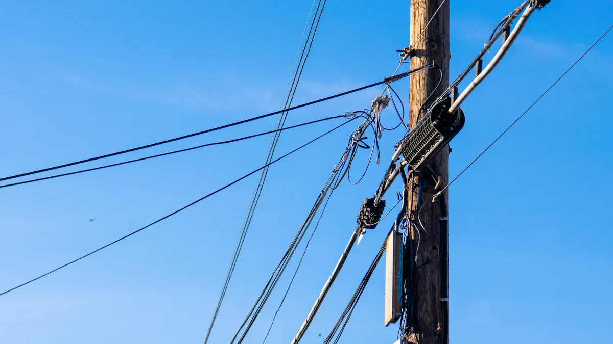
Reliable aerial cable networks begin with strong foundations. Anchoring and mounting components secure the entire infrastructure to utility poles. These foundational Pole Hardware Fittings ensure stability and prevent premature system failure. They bear the initial loads and provide the critical attachment points for all subsequent network elements.
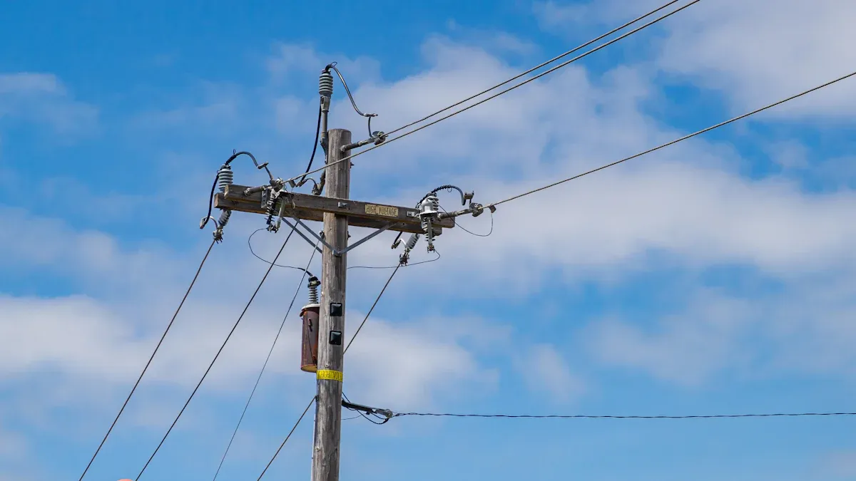
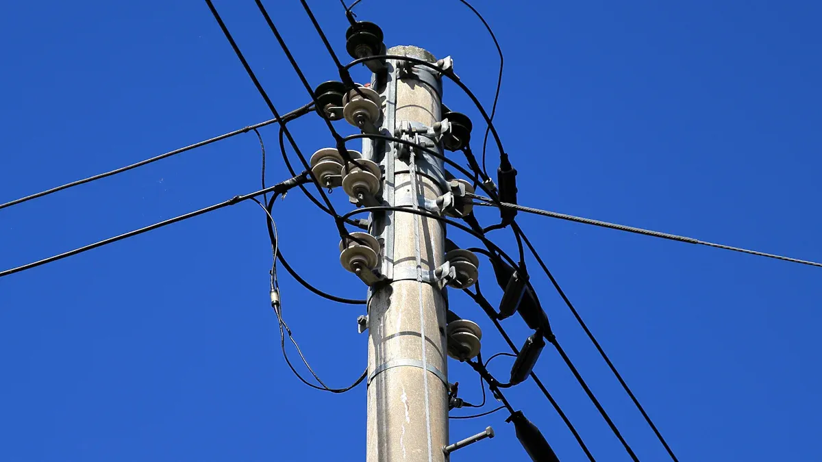
Pole Bands and Clamps: Secure Attachment Points
Pole bands and clamps create essential attachment points on utility poles. These components firmly grip the pole, providing a stable base for mounting cross-arms, brackets, and other equipment. Manufacturers design them for durability and strength, ensuring they withstand environmental stressors. For instance, BAND-IT stainless steel bands and buckles meet ISO 9001 Certification. This certification guarantees rigorous quality standards and consistent process control during manufacturing. Buyers receive documented proof of adherence to high global standards.
High-quality clamps undergo extensive testing to confirm their performance. Testing includes breaking strength assessments, which verify clamps maintain their hold under significant load. Vibration resistance tests simulate conditions like traffic, wind, and heavy use, ensuring long-term durability. Furthermore, corrosion resistance tests expose products to moisture, salt, and temperature fluctuations. These tests guarantee the hardware performs reliably in diverse and challenging environments.
Cross-Arm Braces: Enhancing Structural Integrity
Cross-arm braces provide crucial support to cross-arms, which extend horizontally from utility poles. These braces prevent the cross-arms from sagging, twisting, or failing under the weight of cables and other equipment. They distribute loads effectively, maintaining the structural integrity of the entire pole assembly.
Composite cross-arms can experience structural failure from buckling, torsional action, or creep. These issues often occur when multiaxial loading persists over long periods. To mitigate these problems, engineers propose several design improvements. Adding braced arms, installing sleeves, and incorporating core structures into composite beams significantly enhance resilience.
Research shows that additional support from bracing systems improves creep resistance. Bracing reduces strain during extended tests and enhances elastic and viscoelastic moduli for long-term service. Sleeves, when installed at major member beams, prevent bending deformation and crack propagation. This prevents structural collapse. Numerical studies confirm sleeves improve structural endurance under cable and insulator forces. For example, a one-meter sleeve span on both main members of a cross-arm significantly reduces overall deformation and stress under multiaxial static stress. This extends the cross-arm’s lifespan and lowers maintenance costs.
Integrating core material as a sandwich structure within a cross-arm’s beam also increases structural performance under constant, long-term loading. Retrofitting additional bracing arms restrains elastic buckling, improves external stiffness, and enhances axial compressive load-carrying capacity by distributing forces. Studies indicate bracing can reduce maximum deformation by up to 20.3% and maximum stress by over 5%. These advancements ensure the longevity and reliability of aerial cable networks.
Cable Management Pole Hardware Fittings: Securing and Guiding
Effective cable management is crucial for the longevity and performance of aerial networks. These Pole Hardware Fittings secure and guide cables along their path, preventing damage and maintaining optimal network function. They ensure cables remain in their designated positions, protected from environmental stressors and mechanical strain.
Suspension Clamps: Minimizing Cable Stress
Suspension clamps play a vital role in the long-term reliability of overhead power and communication lines. They securely support fiber optic cables at intermediate spans. This prevents sagging or uncontrolled swinging, which could lead to excessive strain and sheath damage. These clamps distribute the cable’s load while allowing controlled movement. This reduces localized stress points. They also ensure non-conductive contact to prevent corona discharge or electrical tracking. This is crucial for network reliability and safety in high-voltage areas. By maintaining the cable’s designed curvature radius, suspension clamps prevent signal loss in optical fibers. Optical fibers are sensitive to bending, compression, and stress. Dowell manufactures these clamps from corrosion-resistant aluminum alloys and UV-resistant elastomers. They contribute significantly to the lifespan and efficiency of ADSS fiber optic installations.
ADSS suspension clamps mount on utility poles or transmission towers at intermediate points. The ADSS cable rests within a cushioned insert. This insert gently grips the cable without compression. The clamp’s aluminum alloy or stainless-steel body transfers the cable’s vertical load to the pole. This distributes the mechanical load. It prevents stress on any single point of the cable sheath. An elastomer insert provides a sliding and damping effect. This allows slight cable movement during thermal expansion, wind-induced movement, and seismic activity. This internal rubber insert also acts as a shock absorber. It damps aeolian vibrations caused by wind. The non-metallic contact surface insulates the cable from potential corona discharge or tracking. Its operation depends on a workflow that includes installation, cable placement, load bearing, movement control, and long-term protection.
Optimal installation practices for suspension clamps minimize cable stress and prevent premature cable degradation. These practices include:
- Correct clamp selection for the specific cable type and environment.
- Use of armor rods where needed to provide additional protection and support.
- Maintaining proper sag and tension according to engineering specifications.
- Avoiding sharp bends in the cable at the clamp location.
- Checking vibration protection to ensure the clamp effectively dampens movement.
- Ensuring electrical insulation to prevent current leakage or tracking.
- Applying proper torque on bolts for secure, consistent fastening.
- Implementing corrosion protection measures suitable for the local climate.
- Regular inspection to identify and address any issues early.
- Following the manufacturer’s installation recommendations precisely.
- Avoiding improper fitting, which can lead to uneven stress distribution.
Dead-End Grips: Reliable Termination Solutions
Dead-end grips provide reliable termination solutions for aerial cables. They secure the end of a cable or strand to a pole or structure. This prevents the cable from pulling free under tension. These grips are essential for maintaining the structural integrity of the entire network. Dowell offers high-quality dead-end grips designed for various applications.
TREE-GRIP Dead-ends achieve 100% of the published rated breaking strength (RBS) of EHS strands. They are also compatible with various other strand types. These include common grade, Siemens-Martin, high strength, and utilities grade strands. The pull-out strength requirements for dead-end grips vary based on the strand size.
| Model Number | EHS Strand Size | Rated Breaking Strength (RBS) |
|---|---|---|
| RIG325 (PLP Item # TG-1251) | 1/4″ | 6,650 lbs |
| RIG326 (PLP Item # TG-1252) | 5/16″ | 11,200 lbs |
| RIG327 (PL Item # TG-1253) | 3/8″ | 15,400 lbs |

Several factors can cause dead-end grips to fail. Proper selection and installation prevent these issues.
- Improper Sizing: An undersized grip strand diameter leads to slippage, incomplete termination, stress hotspots, or nicking outer wires. Oversized grips do not develop full holding strength. To prevent this, match the real measured diameter. Refer to the manufacturer’s sizing tables for exact strand build and metal grade. Cross-check purchase codes with stock and catalog pages.
- Installation Error: Improper lay direction (RH vs LH), insufficient wrap length, or crossed rods severely impact holding capacity. Train crews on lay matching, start mark alignment, and uniform seating pressure according to manufacturer’s procedures. Utilize specialized tools like torque-limiting wrenches and gauge blocks. Conduct regular field audits with checklists and sample tensile pull tests to ensure compliance.
- Improper Installation: Skipping steps, using wrong tools, or disregarding manufacturer instructions can cause failure. Over-tightening or under-tightening also contributes. Adhere to manufacturer instructions. Provide crucial installer training that explains ‘why’ each step matters.
- Vibration Fatigue: Long-term vibration from wind or traffic induces small cracks that expand over time. This is especially true in dynamic structures. Employ dampers or flex connectors to reduce strain. Monitor vibration levels and fatigue during periodic inspections.
- Environmental Impact: Temperature swings, humidity, pollution, salt, and moisture accelerate rust. Grit grinds metal. Dissimilar metals in contact in moist environments cause galvanic corrosion. Select appropriate materials, such as stainless steel over galvanized in salty air. Use coatings and seals. Pair grips with the local environment. Check weather data. Test grips in specific conditions. Opt for grips with robust coatings for severe environments. Use isolation pads or coatings between dissimilar metals. Pair like metals.
- Long-Term Degradation: General wear over time, rust, cracks, metal spalling, looseness, or slipping under load can occur. Conduct regular inspections (every 6-12 months) for rust, cracks, discoloration, swelling, or abnormal flexion. Replace grips at the first sign of wear or when service life is recommended. Track maintenance and replacement dates.
- Load Dynamics: The grip may be unable to handle variations in wind, weight, and shock loads. Improper sizing for the forces involved is also a cause. Enumerate all forces the structure encounters. Add a margin of safety. Use formulas or online calculators for sizing. Rate grips to hold more than the standard load in high-stress regions, such as windy areas. Test grips with actual weights before use.
- Material Interaction: Using grip and wire materials with different rates of expansion or corrosion leads to galvanic corrosion. An example is a steel grip on aluminum wire in wet climates. Select grip and wire materials in congruence. Use the same metal for both grip and wire. Choose grips with well-established coatings for harsh environments, like saltwater or heavy precipitation.
Strain and Tension Management Pole Hardware Fittings: Maintaining Stability
Aerial cable networks face constant forces from wind, ice, and the weight of the cables themselves. Managing strain and tension is crucial for network stability and longevity. Specialized Pole Hardware Fittings are essential for counteracting these forces. They ensure cables remain taut and secure, preventing sagging, swaying, and potential damage. These components distribute stress evenly, protecting the entire system from premature wear and failure.
Guy Wires and Guy Grips: Counteracting Lateral Forces
Guy wires are critical components in aerial cable networks. They provide essential support to utility poles, counteracting lateral forces from wind, ice, and uneven cable tension. These strong steel cables extend from the pole to an anchor in the ground, creating a stable triangular structure. Guy grips securely attach the guy wires to the pole and the anchor. They ensure a firm, non-slip connection that can withstand significant loads.
Maintaining the integrity of guy wires and guy grips requires regular inspection. Experts recommend frequent inspections, ranging from daily to monthly intervals. During these checks, workers observe the system for any visible defects. Periodic inspections, conducted every 1 to 12 months, depending on activity, service severity, and environment, involve a more detailed examination. Inspectors look for deformed, cracked, or corroded members. They also check for loose bolts or rivets.
A regular inspection schedule is vital. This schedule should consider environmental conditions, usage patterns, and the type of stay rods. Workers perform visual inspections of the entire stay rod system. They look for wear, corrosion, or loose hardware. They also ensure correct tension using suitable measurement tools. Inspection for corrosion is especially important in coastal areas. Workers inspect and test guy wire clamps and fittings. They ensure these components are properly tightened and secure. They also consider the potential impact of environmental factors. These factors include strong winds, seismic activity, and heavy rainfall. During icy or windy conditions, inspectors check for galloping conductors. They ensure anti-galloping devices function as intended. Any loose hardware requires tightening. Corroded or damaged components must be replaced. Keeping detailed records of inspection findings is also important. These records include photographs, tension measurements, and maintenance actions.
Thimbles and Clevises: Protecting Guy Wire Loops
Thimbles and clevises are small but vital components in guy wire assemblies. They protect the guy wire loops from abrasion and stress concentrations. Thimbles act as a buffer. They distribute the load and protect the wire. They ensure even tension distribution across the loop. This prevents localized stress that could lead to failure. Thimbles also reduce friction and mechanical wear. They act as a protective lining inside the wire loop. This minimizes metal-to-metal contact and prevents abrasion. A smooth, contoured inner groove prevents fraying and wear on guy wire loops. This protects against damage from sharp bends and vibrations.
The thimble body protects the eye of the wire rope from bending stress, abrasion, and crushing. Clevis thimbles help distribute tension more evenly. They support the rope’s natural bend radius. This prevents stress concentration at the rope eye. It also maintains full cable strength under load. The thimble’s curved inner surface prevents metal-to-metal contact between the cable and hardware. This minimizes wear and extends the lifespan of the wire rope.
Grounding and Protection Pole Hardware Fittings: Safety and Longevity
Grounding and protection are vital for the safety and longevity of aerial cable networks. These Pole Hardware Fittings safeguard both the infrastructure and personnel. They prevent electrical hazards and shield cables from physical and environmental damage. This ensures continuous, reliable network operation.
Grounding Rods and Clamps: Essential Electrical Safety
Grounding rods and clamps are crucial for electrical safety in aerial cable networks. They protect equipment and personnel from electrical surges and lightning strikes. A grounding rod drives into the earth. It provides a low-resistance path for fault currents. Clamps securely connect the network’s grounding conductors to this rod. This system dissipates dangerous electrical energy safely into the ground. Proper grounding prevents damage to sensitive electronic components. It also reduces the risk of electrocution. This makes the network safer and more reliable.
Cable Guards and Protectors: Shielding Against Damage
Cable guards and protectors shield aerial cables from physical damage. They also protect against environmental stressors. These components prevent abrasion, cuts, and impacts from external forces. They ensure the long-term integrity of the cable infrastructure.
When selecting wire looms for outdoor use, material composition is important.
- Polyethylene (PE) offers natural UV resistance and durability.
- UV-treated Nylon provides strength and flexibility.
Polyurethane stands out for its superior durability. It offers greater impact resistance and higher load capacity. Polyurethane also resists UV degradation, chemicals, and solvents. This makes it more durable than rubber and wood. It suits demanding industrial environments like construction sites.
Manufacturers test and certify products for UV resistance. Look for labels indicating outdoor use or UV stabilization. Ensure the looms tolerate temperature extremes. Sunlight can significantly heat exposed surfaces. Black wire looms are often UV-resistant. They contain carbon black as a UV stabilizer. For other colors, confirm their UV resistance.
UV-resistant cable wraps are essential for outdoor environments. They provide:
- Protection from Sunlight: Prevents cracking and degradation from prolonged UV exposure.
- Salt and Chemical Resistance: Withstands exposure to salt spray, fuels, oils, and detergents.
- Durability in Harsh Environments: Engineered to resist abrasion, vibration, and general wear.
- Temperature Tolerance: Performs reliably across a wide range, typically from –76 °F to 190 °F, accommodating both extreme cold and heat.
The National Electrical Code (NEC) sets specific requirements for outdoor wiring. It emphasizes protection against moisture, corrosion, and physical damage. Cables and conduits used outdoors must be approved and ‘listed’. An authorized testing agency like UL must approve them for their specific application. Standard indoor cables are not suitable. Type UF cables are common for residential outdoor wiring runs.
Specialized Pole Hardware Fittings: Optimizing Performance
Specialized hardware plays a crucial role in optimizing the performance of modern aerial cable networks. These components address the unique demands of advanced cable types, such as fiber optic and All-Dielectric Self-Supporting (ADSS) cables. They ensure precision, reliability, and longevity for high-speed data transmission and robust infrastructure. Selecting the right specialized fittings directly impacts network efficiency and future scalability.
Fiber Optic Cable Management Hardware: Precision for Data
Fiber optic cables require meticulous handling and management due to their delicate nature. Specialized hardware ensures the protection and optimal performance of these critical data pathways. Proper installation practices are paramount for long-term network functionality.
Installers must label cables for easy identification. They should use protective conduits to prevent damage. Bundling cables neatly avoids tangling and improves accessibility for future maintenance.
Effective planning and execution are vital for fiber optic installations.
- Develop a Port Map: Create a detailed inventory sheet and installation guideline. This includes port names, connections, and hardware locations. It allows faster installation and easier troubleshooting.
- Abide by the Cable’s Tensile and Pull Load Rating: Follow specified pull loads and tension capabilities. Use a load monitor during pulling to prevent damage to cables or fibers.
- Reduce the Distance and Pull Lengths When Possible: Run cables the shortest possible distance. This improves signal transfer speed and minimizes the risk of damage during pulling. Use fiber optic lubricant for long pulls and adhere to vertical rise limits.
- Never Pinch, Twist, or Bend Fiber Optic Cables: Avoid pinching, twisting, or exceeding the cable’s permitted bend radius. This protects the fragile internal fibers.
- Practice Cable Management During Installation: Utilize tools like zip ties and Velcro. Use a port map to organize thinner fiber optic cables and keep them safely out of harm’s way.
Minimizing bend radius and pulling tension is crucial. The minimum bend radius indicates the maximum angle a cable can be flexed without damaging its internal glass fibers. Installers must respect this limit to prevent breaks. Similarly, exceeding specified tensile strengths during installation can compromise fiber integrity. Meticulous attention to both bending and tension guidelines is essential to maintain cable functionality.
Proper planning and verification ensure successful fiber optic deployments.
- Plan Slack Storage with Purpose: Utilize purpose-built solutions like baskets, trays, or pedestals for slack management. Avoid loose coils.
- Respect Minimum Bend Radius and Pulling Tensions: Train installers on bend radius and handling requirements. Use hardware that enforces bend radius protection.
- Label and Document Every Segment: Use durable, weather-resistant labels for cables, closures, and ports. Keep records updated as-built.
- Use Modular and Scalable Access Points: Plan for future expansion. Select closures and pedestals that can accommodate additional ports and slack without full replacement.
- Inspect and Verify Work Before Closure: Before finalizing installations, inspect cable placement. Ensure compliance with bend radius, labeling, and slack storage guidelines.
ADSS Cable Hardware: Supporting All-Dielectric Self-Supporting Cables
All-Dielectric Self-Supporting (ADSS) cables offer unique advantages for aerial networks, especially near high-voltage lines. Their design eliminates metallic components, making them fully dielectric and immune to electromagnetic interference. This allows installation near high-voltage lines, typically 10-20 feet below phase conductors, without electrical interference. However, their unique mechanical and electrical properties demand specialized hardware.
ADSS cables possess distinct characteristics that influence hardware design:
- Self-supporting design: ADSS cables bear all mechanical loads themselves. This includes weight, wind, ice, and tension. Traditional cables use separate messenger wires. This necessitates hardware capable of managing these loads over spans up to 1,200 meters.
- High tensile strength: The cable withstands significant pulling tension, for example, up to 600 pounds force during installation. Operational span tension also requires specialized tension grips and suspension clamps. These must match the cable’s rated tensile strength (RTS).
- Specific bending radius requirements: Strict control over bending radius is crucial to prevent fiber breakage. This means 20 times cable diameter during installation and 10 times during operation. This influences the design of sheaves and other pulling equipment. They must meet these diameter ratios.
- Sag and tension management: Precise calculation and management of sag are critical. For example, 1% installation sag. Hardware and installation equipment, like bull wheel tensioners with monitoring systems, achieve and maintain the correct span tension. This prevents issues like microbending losses or excessive sag.
- Risk of dry-band arcing and corona discharge: Despite being dielectric, improper positioning in intense electrical fields, especially on lines exceeding 69 kV, can degrade the cable jacket. This emphasizes the need for precise installation techniques and potentially specialized track-resistant jackets. Hardware must not compromise these.
The unique properties of ADSS cables directly influence the design of their supporting hardware:
| Property | Influence on Hardware Design |
|---|---|
| Self-supporting design & High Tensile Strength | Requires specialized suspension clamps and tension grips. These precisely match the cable’s diameter and Rated Tensile Strength (RTS). They bear all mechanical loads and manage span tension. Hardware is not interchangeable. |
| Weight, Wind, Ice Accumulation, Tension Forces | Necessitates vibration dampers to mitigate dynamic loads and prevent cable damage. Hardware must handle these environmental stresses. |
| Specific Bending Radius Requirements | Demands sheaves with diameters meeting specific ratios to the cable diameter (e.g., 20x during installation). This prevents fiber breakage. |
| Precise Sag and Tension Management | Requires bull wheel tensioners with brake and tension monitoring systems. It also requires pulling equipment with breakaway swivels. These control pulling tension and achieve designed span sag. |
| All-dielectric nature & High-voltage environment | The cable itself is dielectric. However, the need to avoid dry-band arcing and corona discharge implies hardware should not introduce points of electrical stress. It also should not compromise the cable’s track-resistant jacket. Installation manuals emphasize hardware designed based on ADSS characteristics. This ensures compatibility in electrical fields. |
ADSS cable hardware must withstand significant mechanical loads from environmental factors. These include wind, ice, and temperature extremes. These factors vary geographically and require quantification during specification. The National Electrical Safety Code (NESC) classification system categorizes wind loading into Light, Medium, and Heavy districts. Cables need design for the worst-case combinations of temperature, ice load, and wind.
Medium loading represents typical conditions across most of North America. It involves 6.4mm radial ice with a 19 m/s wind. Heavy loading zones, found in coastal areas and mountain passes, can double or triple cable stress compared to light districts. Ice accumulation significantly impacts cable tension. A 10mm ice layer increases effective cable diameter by 20mm. It also adds substantial weight. This can potentially triple tension during storms due to increased wind profile and weight. Installation environments should be classified using NESC loading districts or local equivalents. Obtain historical weather data, including maximum wind speeds, ice accumulation, and temperature extremes, for the region.
High-quality fittings significantly impact aerial network performance. Robust components ensure future-proof infrastructure. They provide long-term stability and reliability. Dowell offers reliable solutions for these needs. Consider professional consultation or further research to select optimal hardware choices.
FAQ
What makes Dowell’s pole hardware fittings reliable?
Dowell ensures reliability through rigorous testing. They use quality materials. Their products meet international standards like ISO 9001. This guarantees consistent performance and durability.
Why are suspension clamps important for fiber optic cables?
Suspension clamps minimize cable stress. They prevent sagging and damage. These clamps distribute load evenly. They also protect against bending and vibration. This ensures long-term signal integrity.
How do dead-end grips prevent cable failure?
Dead-end grips secure cable ends to poles. They prevent slippage under tension. Proper sizing and installation are crucial. This ensures the grip matches the cable’s strength. It maintains network integrity.
Post time: Jan-09-2026