Direct burial fiber optic cable installation involves placing cables directly into the ground without additional conduit, ensuring efficient and secure data transmission for urban infrastructure. This method supports the growing demand for high-speed fiber optic internet cable networks, which form the backbone of modern cities. Proper installation ensures durability and minimizes network disruptions. Dowell, a leader in fiber optic solutions, specializes in advanced technologies like single mode duplex fiber optic cable systems. Eric, Manager of the Foreign Trade Department, leverages his expertise to deliver innovative solutions tailored to urban needs.
Contact Eric on Facebook for expert guidance.
Key Takeaways
- Direct burial fiber optic cables go underground without extra pipes. This saves money and works well in cities.
- Planning and checking the soil are very important for success. Knowing the soil type helps pick the right cables and methods.
- Regular inspections and care keep fiber optic networks working well. Checking often can stop expensive problems later.
- Armored cables and safety tools, like warning tapes, make cables stronger. These protect them from damage and bad weather.
- Following rules during setup and testing makes networks work better. It also ensures they meet quality standards.
Overview of Direct Burial Fiber Optic Cable
Definition and Purpose
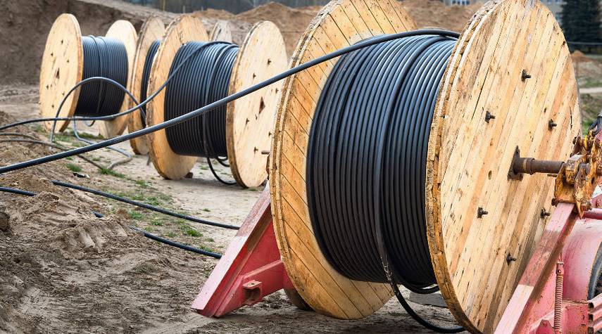
Direct burial fiber optic cable refers to a specialized type of cable designed for underground installation without requiring additional conduits or protective trays. This method ensures secure and efficient data transmission, making it ideal for urban infrastructure projects. By embedding the cables directly into the soil, cities can establish robust communication networks that support high-speed internet and advanced technologies. The streamlined installation process reduces costs and accelerates deployment timelines, making it a preferred choice for modern urban development.
Construction Features and Durability
Direct burial fiber optic cables are engineered to withstand harsh environmental conditions and physical stress. Their ruggedized construction includes steel armor, high-density polyethylene jackets, and water-blocking layers, ensuring protection against water ingress, dirt, and extreme temperatures. These cables are available in various types, such as armored loose tube, non-armored loose tube, and ribbon cables, tailored to specific soil conditions.
| Specification/Feature | Description |
|---|---|
| Cable Construction | Ruggedized jacket and armor for water ingress protection and dirt shedding capabilities. |
| Installation Method | Direct burial without the need for additional pipes or trays. |
| Environmental Considerations | Resilient to flooding, extreme heat, and harsh climates. |
| Maintenance Practices | Requires less maintenance due to fewer hazards compared to aerial installations. |
| Common Cable Types for Burial | Armored loose tube, non-armored loose tube, and ribbon cables based on soil conditions. |
| Durability Features | Steel armor, high-density polyethylene, and water-blocking layers to maintain signal integrity. |
| Cost Efficiency | Saves up to 75% in installation time and cost compared to conduit or aerial deployments. |
These features ensure long-term reliability and minimal maintenance, making direct burial fiber optic cables a cost-effective solution for urban infrastructure.
Benefits for Urban Infrastructure
Direct burial fiber optic cables offer transformative benefits for urban environments. Their ability to deliver high-speed internet enhances communication networks, driving economic growth and technological innovation. Cities that adopt this installation method experience improved operational efficiency across industries, better data management, and increased productivity.
| Case Study | Benefits |
|---|---|
| Citywide Fiber Optic Network Upgrade | Enhanced internet speeds, improved communication infrastructure, economic growth |
| Residential Development | Reliable and fast internet, access to advanced home technologies, increased property value |
| Industrial Applications | Improved operational efficiency, better data management, increased productivity, enhanced worker safety |
By integrating direct burial fiber optic cables, urban areas can support advanced technologies, improve connectivity, and foster sustainable development.
Planning and Preparation
Route Planning and Site Surveying
Effective route planning ensures the seamless installation of direct burial fiber optic cable in urban environments. Professionals often rely on mapping tools and digital survey data to optimize cable pathways. Engaging with local experts provides insights into existing conduits and pathways, reducing installation challenges. High-level and low-level designs help visualize network layouts and estimate costs. On-site visits allow teams to identify physical obstacles, assess the landscape, and refine plans.
Tip: Early collaboration with urban planners and utility providers can prevent conflicts with existing infrastructure and streamline the installation process.
Evaluating Soil Conditions and Water Table Levels
Understanding soil conditions is critical for successful cable installation. Soil composition affects trenching methods and burial depth standards. Loose or sandy soils may require additional reinforcement, while rocky terrains demand specialized excavation techniques. Water table levels also play a significant role. High water tables necessitate cables with enhanced water-blocking layers to prevent signal degradation. Engineers often conduct soil tests and hydrological surveys to ensure the chosen cable type aligns with environmental conditions.
| Strategy | Description |
|---|---|
| Requirements Gathering | Essential for understanding user needs and aligning on technical and business considerations. |
| Site Surveys | Assess physical infrastructure and identify potential obstacles in the coverage area. |
| Feasibility Studies | Evaluate economic and technical viability of the proposed network. |
| Network Topology Design | Focus on cable routing, resilience, and automation for optimal performance and reliability. |
Regulatory Compliance and Permits
Navigating regulatory requirements is a vital step in the preparation phase. Urban areas often have strict guidelines for underground installations to protect public safety and existing infrastructure. Teams must secure permits from local authorities before beginning excavation. Compliance with environmental regulations ensures minimal ecological impact. Documentation of the installation plan, including trenching methods and burial depths, helps meet legal standards. Regular communication with regulatory bodies fosters transparency and avoids project delays.
Installation Process
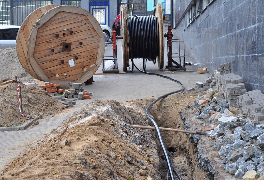
Trenching and Excavation Methods
Trenching and excavation are critical steps in the installation of direct burial fiber optic cable. These processes involve creating a pathway in the ground to securely embed the cables. Selecting the appropriate excavation technique depends on the urban environment, soil conditions, and existing infrastructure.
| Excavation Technique | Description | Performance Metric |
|---|---|---|
| Ground Penetrating Radar | Identifies underground services and formations. | Prevents accidental damage to existing utilities. |
| Hand Excavation | Uncovers known services before mechanical excavation. | Reduces the risk of damaging existing utilities. |
| Trench Support Methods | Includes sloping, trench boxes, and shoring for trenches deeper than 1.2m. | Ensures worker safety and prevents cave-ins. |
| Micro-trenching | Cuts a narrow slot in the road surface for cable installation. | Minimizes disruption and accelerates deployment. |
| Backfill Compaction | Compacts material in layers not exceeding 300mm. | Ensures trench density matches or exceeds that of virgin soil. |
Micro-trenching has gained popularity in urban areas due to its minimal disruption to roadways and faster deployment times. However, for deeper installations, trench support methods like shoring and trench boxes are essential to ensure worker safety and prevent cave-ins. Proper backfill compaction is equally important to maintain the integrity of the trench and prevent future ground settling.
Note: Employing ground-penetrating radar before excavation can significantly reduce the risk of damaging existing underground utilities.
Burial Depth Standards for Urban Areas
The depth at which direct burial fiber optic cable is installed plays a crucial role in its longevity and performance. Industry standards recommend varying burial depths based on the environment and specific conditions.
| Environment Type | Recommended Burial Depth |
|---|---|
| Urban Areas | 24–36 inches (60–90 cm) |
| Rural Areas | 36–48 inches (90–120 cm) |
| Conduit-Installed Cables | 18–24 inches (45–60 cm) |
| Under Roadways/Railways | 48+ inches (120+ cm) |
| Frost-Prone Regions | Below the frost line |
In urban settings, cables are typically buried at depths of 24–36 inches to protect them from surface activities such as construction or landscaping. For areas under roadways or railways, deeper installations exceeding 48 inches are necessary to withstand heavy loads and vibrations. In frost-prone regions, cables must be buried below the frost line to prevent damage caused by freezing and thawing cycles.
Adhering to these standards ensures that the cables remain secure and functional, even in challenging environments. Engineers must also consider local regulations and environmental factors when determining the appropriate burial depth.
Cable Laying Techniques
Efficient cable laying techniques are essential for the successful installation of direct burial fiber optic cable. Proper planning and execution minimize the risk of damage and ensure optimal performance. The following benchmarks guide the process:
- Proper Planning: A detailed plan helps avoid errors during installation. Route assessments ensure cables are free from hazards such as sharp objects or existing utilities.
- Testing Cables: Conducting pre-installation and post-installation tests verifies the quality and functionality of the cables.
- Determining Length: Accurate measurements prevent issues related to ordering excess or insufficient cable.
During the laying process, cables should be handled with care to avoid bending beyond their minimum bend radius, which could compromise signal integrity. Specialized equipment, such as cable plows or trenchers, can streamline the process and reduce manual labor. After laying the cables, teams must ensure they are properly aligned and tensioned to prevent future issues.
Tip: Using markers or warning tapes above the cables during backfilling can help identify their location during future excavations, reducing the risk of accidental damage.
Backfilling and soil compaction
Backfilling and soil compaction are critical steps in the installation of direct burial fiber optic cables. These processes ensure the stability and longevity of the cable infrastructure by protecting it from environmental and mechanical stresses. Proper execution minimizes the risk of future ground settling, which could compromise the cable’s performance or lead to costly repairs.
Importance of Backfilling
Backfilling involves refilling the trench after the cable has been laid. This step is essential for safeguarding the cable and restoring the ground to its original condition. The choice of backfill material significantly impacts the cable’s durability and performance.
Key considerations for backfilling include:
- Material Selection: Use clean, fine-grained soil or sand free from sharp objects or debris. Avoid materials that could damage the cable jacket.
- Layering: Apply backfill in layers to ensure even distribution and prevent voids.
- Protective Measures: Place a warning tape or marker above the cable to alert future excavators.
Tip: Using sand as the initial backfill layer provides a cushion for the cable, reducing the risk of damage from external forces.
Soil Compaction Techniques
Soil compaction follows backfilling and involves compressing the soil to eliminate air pockets. This process enhances the soil’s density, providing a stable environment for the cable. Proper compaction prevents ground settling, which could expose the cable to external hazards.
Common soil compaction methods include:
- Manual Compaction: Suitable for small-scale projects or areas with limited access. Workers use hand tampers to compact the soil.
- Mechanical Compaction: Ideal for larger projects. Equipment like vibratory rollers or plate compactors ensures uniform density.
- Layer-by-Layer Compaction: Compacting the soil in layers no thicker than 6 inches ensures optimal density and stability.
| Compaction Method | Best Use Case | Advantages |
|---|---|---|
| Manual Compaction | Small trenches or tight spaces | Cost-effective and easy to control |
| Mechanical Compaction | Large-scale urban installations | Fast and highly efficient |
| Layer-by-Layer Compaction | All trench types | Ensures uniform density |
Best Practices for Backfilling and Compaction
Adhering to best practices ensures the success of backfilling and compaction efforts. These include:
- Moisture Control: Maintain optimal soil moisture levels to facilitate compaction. Dry soil may crumble, while overly wet soil can become unstable.
- Testing: Conduct density tests to verify that the compaction meets industry standards.
- Monitoring: Regularly inspect the site during and after compaction to identify and address any issues.
Note: Neglecting proper backfilling and compaction can lead to uneven ground surfaces, increased maintenance costs, and potential damage to the cable.
By following these guidelines, urban infrastructure projects can achieve a stable and reliable foundation for direct burial fiber optic cables. This ensures long-term performance and reduces the likelihood of future disruptions.
Protection and Maintenance
Armored Protection and Physical Safeguards
Direct burial fiber optic cable installations require robust protection to ensure long-term reliability. Armored cables provide an essential layer of defense against physical damage caused by environmental factors, construction activities, or accidental excavation. These cables feature steel or aluminum armor that shields the fiber core from external stress, preserving signal integrity.
Physical safeguards complement armored protection by creating barriers that deter unauthorized access or accidental damage. Common safeguards include:
- Warning Tapes: Placed above buried cables to alert future excavators.
- Protective Conduits: Used in areas with high mechanical stress, such as under roadways.
- Cable Markers: Installed at regular intervals to indicate the cable’s location.
Urban infrastructure projects often integrate these measures to enhance the durability of fiber optic networks. Combining armored cables with physical safeguards ensures uninterrupted data transmission and reduces maintenance costs.
Routine Inspections and Monitoring
Routine inspections play a critical role in maintaining the performance of direct burial fiber optic cable systems. Regular monitoring helps identify potential issues before they escalate, ensuring network reliability. Maintenance activities include visual inspections, signal testing, and equipment checks.
| Maintenance Activity | Frequency |
|---|---|
| External Fiber Inspection | Annual |
| Connector Inspection | Annual |
| Feedthrough Examination | During scheduled transformer inspections |
| Equipment Cabinet Inspection | Quarterly |
| Sensor Junction Inspection | During maintenance outages |
| Signal Level Verification | Annual |
| Continuity Testing | Annual |
| Connection Loss Measurement | Biennial |
| OTDR Testing | Biennial |
| Communications Interface Check | Annual |
| Software Updates | As per manufacturer recommendations |
| Database Maintenance | Quarterly |
| Configuration Backup | Monthly |
| Security Updates | Timely |
| User Account Management | Semi-annual |
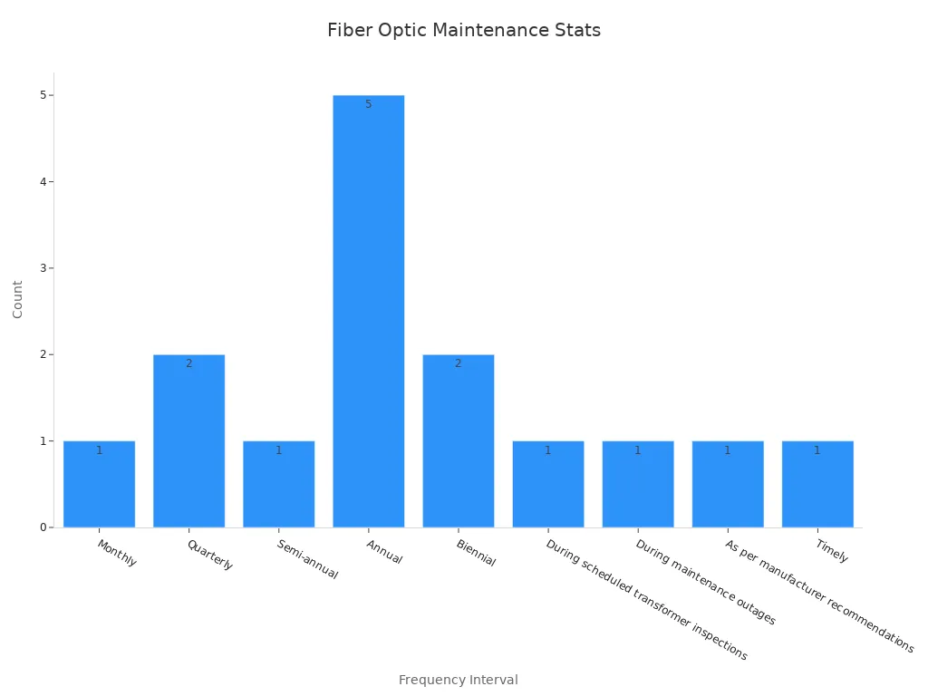
Inspection frequency varies based on the type of activity and environmental conditions. For example, external fiber inspections are conducted annually, while equipment cabinet checks occur quarterly. Advanced tools like Optical Time Domain Reflectometers (OTDRs) enable precise signal testing, ensuring optimal performance.
Tip: Maintaining detailed records of inspection activities helps track system health and facilitates timely interventions.
Troubleshooting and Repair Strategies
Effective troubleshooting and repair strategies minimize downtime and ensure the seamless operation of fiber optic networks. Technicians use diagnostic tools to pinpoint issues such as signal loss, physical damage, or connectivity disruptions. Common troubleshooting methods include:
- Signal Testing: Verifies the integrity of data transmission.
- Visual Inspection: Identifies physical damage to cables or connectors.
- Continuity Testing: Confirms uninterrupted signal flow.
Repair strategies depend on the nature of the issue. For minor damages, technicians may replace connectors or splice broken fibers. Severe cases, such as extensive cable damage, require segment replacement. Preventive measures, including routine inspections and armored protection, reduce the likelihood of major repairs.
Note: Using high-quality materials and adhering to industry standards during installation simplifies future troubleshooting and repairs.
Environmental and Urban Considerations
Managing Diverse Soil Types
Urban environments feature a variety of soil types, each presenting unique challenges for direct burial fiber optic cable installation. Engineers must assess soil composition to determine the best installation strategies.
- Clay: Dense and water-retentive, clay can crush cables under pressure.
- Sand: While it drains quickly, sand shifts easily, potentially exposing cables.
- Loam: A balanced mix of sand, silt, and clay, loam offers stability and is often ideal for cable burial.
- Rocky Soil: Hard to trench, rocky soil may damage cables during installation.
- Silt: Fine and water-retentive, silt risks shifting and washouts.
To mitigate these challenges, teams often use water-tight conduits and add gravel or sand for drainage in unstable soils. Routing cables away from flood-prone areas further reduces risks.
Tip: Conducting soil tests before installation ensures the selection of appropriate cable types and protective measures.
Addressing Water Table Challenges
High water tables pose significant risks to buried fiber optic cables, including water ingress and signal degradation. Engineers must evaluate hydrological conditions to design effective solutions.
Strategies include:
- Installing cables with enhanced water-blocking layers.
- Using gravel or sand to improve drainage around the cable.
- Avoiding low-lying paths prone to flooding.
In areas with fluctuating water tables, protective conduits offer additional safeguards. These measures ensure the cables remain functional despite environmental challenges.
Minimizing Ecological and Urban Impact
Cable installation in urban areas must balance infrastructure development with environmental preservation. Teams prioritize sustainable practices to minimize disruption.
- Routing cables to avoid wetlands and sensitive ecosystems.
- Hand-digging around tree roots to prevent damage.
- Restoring land post-installation to maintain ecological balance.
Urban planning reports often emphasize the importance of reducing construction-related disturbances. By adhering to these practices, cities can expand their fiber optic networks while preserving their natural and urban landscapes.
Note: Incorporating eco-friendly methods not only protects the environment but also enhances community support for infrastructure projects.
Testing and Quality Assurance
Pre-installation Testing Protocols
Pre-installation testing ensures that fiber optic cables meet quality standards before deployment. These protocols verify the physical, mechanical, and transmission characteristics of the cables, reducing the risk of performance issues during operation. Testing in controlled environments allows engineers to identify and address potential defects early.
| Testing Characteristic | Purpose |
|---|---|
| Geometrical Characteristics | Assesses core diameter, cladding diameter, concentricity error, and non-circularity. |
| Transmission Characteristics (Attenuation) | Evaluates signal loss properties of uncabled optical fibers. |
| Transmission Characteristics (Chromatic Dispersion) | Analyzes data transmission accuracy over varying wavelengths. |
| Transmission Characteristics (Polarization Mode Dispersion) | Examines data integrity in optical communications. |
| Transmission Characteristics (Cut-Off Wavelength) | Determines effective operational range of the fiber. |
| Transmission Characteristics (Fiber Macro Bend Loss) | Scrutinizes susceptibility to macro bends to prevent signal loss. |
| Mechanical Characteristics | Evaluates tensile strength, proof test, and fatigue performance for durability assurance. |
| Environmental Characteristics of Fiber | Tests moisture and temperature resistance for robustness. |
| Color Qualification | Assesses color stability and accuracy for consistent product quality. |
| Material Properties | Analyzes mechanical and thermal properties for application suitability. |
These tests ensure that cables can withstand environmental and operational stresses, guaranteeing long-term reliability.
Post-installation Performance Testing
Post-installation testing validates the functionality and performance of the installed fiber optic network. Technicians use advanced tools to measure signal quality and identify potential issues. Key procedures include:
| Testing Procedure | Purpose |
|---|---|
| Continuity and Polarity Testing | Ensures that the fiber optic connections are correctly established and functioning. |
| End-to-End Insertion Loss Testing | Measures the total loss of signal through the fiber optic cable to ensure it meets specifications. |
| OTDR Testing | Verifies the quality of individual splices in long outside plant cables. |
| Transmitter and Receiver Power Testing | Confirms that the system is operating properly by measuring the power levels. |
| Insertion Loss Measurement | Essential for determining if the cable plant is within the loss budget before installation acceptance. |
These tests confirm that the network meets design specifications and operates efficiently.
Ensuring Compliance with Industry Standards
Adhering to industry standards ensures the quality and reliability of fiber optic installations. The IEC 61300-3-35 standard plays a critical role in maintaining cleanliness and performance in fiber optic connections. It provides objective grading criteria for cleanliness inspections, eliminating subjective judgment. Certification requirements vary based on connector type, fiber size, and defect categories, such as scratches and contamination.
Tip: Following these standards not only ensures compliance but also enhances the durability and efficiency of fiber optic networks.
By implementing rigorous testing and adhering to established benchmarks, urban infrastructure projects can achieve robust and reliable communication networks.
Successful installation and maintenance of direct burial fiber optic cable rely on meticulous planning, precise execution, and ongoing care. Key steps include route planning, soil evaluation, and adherence to industry standards during trenching, cable laying, and backfilling. Routine inspections and robust protection measures further enhance network reliability.
This installation method offers unparalleled benefits for urban infrastructure. Its durability, cost-effectiveness, and ability to support high-speed data transmission make it indispensable for modern cities. With proper installation, these cables can serve urban networks for decades, as validated by their robust construction features and long service life.
Adopting best practices ensures long-term reliability and minimizes disruptions. Dowell, a trusted leader in fiber optic solutions, provides expert guidance for seamless implementation. Contact Eric, Manager of the Foreign Trade Department, for tailored solutions that meet your urban infrastructure needs.
Connect with Eric on Facebook to explore Dowell’s innovative fiber optic solutions.
FAQ
What is the recommended burial depth for direct burial fiber optic cables in urban areas?
Industry standards suggest burying cables at depths of 24–36 inches in urban environments. This depth protects cables from surface activities like construction and landscaping while ensuring long-term reliability.
How can soil conditions affect the installation process?
Soil composition determines trenching methods and cable type. Loose soils may require reinforcement, while rocky terrains demand specialized excavation techniques. Engineers conduct soil tests to align installation strategies with environmental conditions.
What tools are used for testing fiber optic cables post-installation?
Technicians use Optical Time Domain Reflectometers (OTDRs) to verify splice quality and measure signal loss. Continuity testers and insertion loss meters ensure the network meets design specifications and operates efficiently.
How do armored cables enhance protection for buried fiber optics?
Armored cables feature steel or aluminum layers that shield the fiber core from physical damage. This construction prevents signal degradation caused by environmental stress, accidental excavation, or construction activities.
Why is routine inspection important for fiber optic networks?
Regular inspections identify potential issues early, ensuring uninterrupted data transmission. Activities like signal testing, visual checks, and equipment maintenance enhance network reliability and reduce repair costs.
Post time: May-16-2025